
Page 41 - Modern Control of DC-Based Power Systems
P. 41
6 Modern Control of DC-Based Power Systems
r L
I
E V C (P+ψ)/V
Stabilizing condition
Figure 1.5 Load side stabilizing control.
r L I
E C V Z V P/V
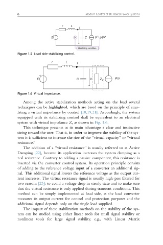
Figure 1.6 Virtual impedance.
Among the active stabilization methods acting on the load several
techniques can be highlighted, which are based on the principle of emu-
lating a virtual impedance by control [18,19,21]. Accordingly, the system
equipped with its stabilizing control shall be equivalent to an electrical
system with virtual impedance Z v as shown in Fig. 1.6.
This technique presents as its main advantage a clear and instinctive
sizing toward the user. That is, in order to improve the stability of the sys-
tem it is sufficient to increase the size of the “virtual capacity” or “virtual
resistance.”
The addition of a “virtual resistance” is usually referred to as Active
Damping [22], because its application increases the system damping as a
real resistance. Contrary to adding a passive component, this resistance is
inserted via the converter control system. Its operation principle consists
of adding to the reference voltage input of a converter an additional sig-
nal. This additional signal lowers the reference voltage as the output cur-
rent increases. The virtual resistance signal is usually high-pass filtered for
two reasons [23]: to avoid a voltage drop in steady state and to make sure
that the virtual resistance is only applied during transient conditions. This
method can be simply implemented at load side, as the load converter
measures its output current for control and protection purposes and the
additional signal depends only on the single load supplied.
The impact of these stabilization methods on the stability of the sys-
tem can be studied using either linear tools for small signal stability or
nonlinear tools for large signal stability, e.g., with Linear Matrix