
Page 38 - Modern Control of DC-Based Power Systems
P. 38
Overview—Voltage Stabilization of Constant Power Loads 3
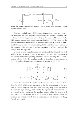
r L
I I CPL
E C V R CPL 2P/V 0
Figure 1.3 Electrical system containing a Constant Power Load, equivalent circuit
around operating point.
One can conclude that a CPL around its operating point has a behav-
ior similar to that of a negative resistance in parallel with a constant cur-
rent source. The diagram corresponding to the electrical behavior of the
CPL around an operating point is depicted in Fig. 1.3. The output of the
source converter is represented by the voltage source E, which is inter-
faced through a filter circuit consisting of the equivalent series resistor of
the inductor r, the inductor L, and the capacitor C; where V denotes the
voltage over the capacitor.
In order to have a mathematical observation of the effect of the CPL
and R CPL on the network and to exclusively consider the variations of
the system around the operating point lead toward omitting the DC com-
ponent of Eq. (1.3), the resultant model is described in accordance to
Eq. (1.4) and its characteristic polynomial is written in Eq. (1.5).
21 1
2 3
_ 6 C 7
V CR CPL 7 V
6 (1.4)
I _ 5 6 21 2 r 5 I
7
4
L L
r 1 1 r
2
P λðÞ 5 λ 1 1 λ 1 1 1 (1.5)
L CR CPL LC R CPL
From the characteristic polynomial, one can deduce the relation-
ship Eq. (1.6) which states the criteria for the eigenvalues of the sys-
tem to have a negative real part. The first inequality holds because of
the negative sign of R CPL and usually the equivalent series resistor r is
very small when comparing the absolute values, while the second will
not always be respected since an increase in load power causes an
increase in current which has as consequence an increase of R CPL
(which goes to 0).