
Page 137 - Modern Optical Engineering The Design of Optical Systems
P. 137
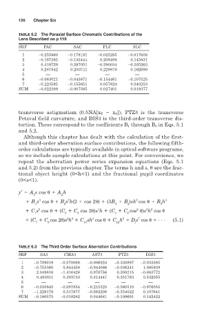
120   Chapter Six

        TABLE 6.2  The Paraxial Surface Chromatic Contributions of the
        Lens Described on p 119
        SRF       PAC         SAC        PLC         SLC
          1     –0.255960   –0.178181  –0.025295   –0.017608
          2     –0.187385   –0.130444   0.209488    0.145831
          3      0.419729    0.297051  –0.290034   –0.205263
          4      0.287842    0.203711   0.229879    0.162690
          5        ––          ––         ––          ––
          6     –0.063021   –0.043871  –0.154461   –0.107525
          7     –0.223595   –0.155651   0.057824    0.040253
        SUM     –0.022389   –0.007385   0.027401    0.018377


        transverse astigmatism (0.5NA[x T   x S ]), PTZ3 is the transverse
        Petzval field curvature, and DIS3 is the third-order transverse dis-
        tortion. These correspond to the coefficients B 1 through B 5 in Eqs. 5.1
        and 5.2.
          Although this chapter has dealt with the calculation of the first-
        and third-order aberration surface contributions, the following fifth-
        order calculations are typically available in optical software programs,
        so we include sample calculations at this point. For convenience, we
        repeat the aberration power series expansion equations (Eqs. 5.1
        and 5.2) from the previous chapter. The terms h and s,   are the frac-
        tional object height (0<h<1) and the fractional pupil coordinates
        (0<s<1).

        y′   A s cos    A h
              1          2
                            2
                3
                                                      2
             B s cos    B s h(2   cos 2 )   (3B   B )sh cos    B h 3
               1          2                   3    4            5
                5
                                                          3 2
                                       4
                                                       2
             C s cos    (C   C cos 2 )s h   (C   C cos  )s h cos
               1          2    3              4    6
                           2 3
                                                 5
                                                       7
                                     4
             (C   C cos 2 )s h   C sh cos    C h   D s cos     . . .  (5.1)
               7    8             10           12     1
        TABLE 6.3  The Third Order Surface Aberration Contributions
        SRF      SA3      CMA3       AST3       PTZ3      DIS3
         1    –0.709019  –0.070068  –0.006924  –0.330897  –0.033385
         2    –0.755360   0.844458  –0.944066  –0.036241  1.095939
         3     2.049816  –1.416428  0.978756   0.300215  –0.883772
         4     0.493011   0.393733  0.314447   0.351763  0.532055
         5       ––         ––        ––         ––        ––
         6    –0.035845  –0.087854  –0.215325  –0.060510  –0.676055
         7    –1.229178   0.317877  –0.082206  –0.334022  0.107641
        SUM   –0.186575  –0.018282  0.044681  –0.109691  0.142422