
Page 156 - Modern Optical Engineering The Design of Optical Systems
P. 156
Prism and Mirror Systems 139
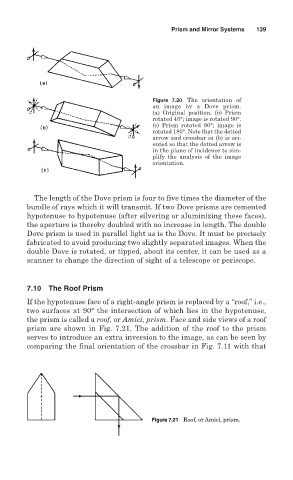
Figure 7.20 The orientation of
an image by a Dove prism.
(a) Original position. (b) Prism
rotated 45°; image is rotated 90°.
(c) Prism rotated 90°; image is
rotated 180°. Note that the dotted
arrow and crossbar in (b) is ori-
ented so that the dotted arrow is
in the plane of incidence to sim-
plify the analysis of the image
orientation.
The length of the Dove prism is four to five times the diameter of the
bundle of rays which it will transmit. If two Dove prisms are cemented
hypotenuse to hypotenuse (after silvering or aluminizing these faces),
the aperture is thereby doubled with no increase in length. The double
Dove prism is used in parallel light as is the Dove. It must be precisely
fabricated to avoid producing two slightly separated images. When the
double Dove is rotated, or tipped, about its center, it can be used as a
scanner to change the direction of sight of a telescope or periscope.
7.10 The Roof Prism
If the hypotenuse face of a right-angle prism is replaced by a “roof,” i.e.,
two surfaces at 90° the intersection of which lies in the hypotenuse,
the prism is called a roof, or Amici, prism. Face and side views of a roof
prism are shown in Fig. 7.21. The addition of the roof to the prism
serves to introduce an extra inversion to the image, as can be seen by
comparing the final orientation of the crossbar in Fig. 7.11 with that
Figure 7.21 Roof, or Amici, prism.