
Page 153 - Modern Optical Engineering The Design of Optical Systems
P. 153
136 Chapter Seven
is tilted in a meridian 90° to the original plate, by introducing either
a weak cylinder or a tilted spherical surface, or by wedging the plate.
7.9 The Right-Angle Prism
The right-angle prism, with angles of 45°–90°–45°, is the building
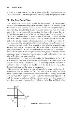
block of most nondispersing prism systems. Figure 7.15 shows a para-
llel bundle of rays passing through such a prism, entering through one
face, reflecting from the hypotenuse face, and leaving through the second
face. If the rays are normally incident on the face of the prism, they are
deviated through an angle of 90°. At the hypotenuse face, the rays have
an angle of incidence of 45° so that they are subject to total internal
reflection. If the entrance and exit faces are low-reflection-coated, this
makes the prism a highly efficient reflector for visual usage since the
only losses are the absorption of the material and the reflection losses
at the faces which total a few percent or less. (In the ultraviolet and
infrared portions of the spectrum, the absorption of a prism may be
quite objectionable.) It can be seen that the total internal reflection is
limited to rays which have angles of incidence greater than the critical
angle, and many prism systems are made of high-index glass to permit
total reflection over larger angles.
By unfolding the prism, as indicated by the dashed lines in Fig. 7.16,
it is apparent that the prism is the equivalent of a glass block with
parallel faces, with a thickness equal to the length of the entrance or
exit faces. The equivalent air thickness of the block is, of course, this
thickness divided by the index of the prism.
If the 45°–90°–45° prism is used with the light beam incident on the
hypotenuse face as shown in Fig. 7.17, the light is totally reflected
twice and the rays emerge in the opposite direction, having been devi-
ated through 180°. Figure 7.17 also indicates the unfolded prism path
and the image orientation of this prism. Notice that the image has
been inverted, top to bottom, but not left to right. The unfolded prism
Figure 7.15 Right-angle prism.