
Page 149 - Modern Optical Engineering The Design of Optical Systems
P. 149
132 Chapter Seven
Figure 7.10 A useful technique in
determining the orientation of a
reflected image is to visualize
the image as a pencil “bouncing”
off a solid wall as it moves along
the system axis.
and the blunt end continuing in the original direction, and the third
shows the pencil in the new orientation after the reflection. If the process
is repeated with the pencil perpendicular to the plane of the paper, the
orientation of the other meridian of the image can be determined. The pro-
cedure can then be repeated through each reflection in the system.
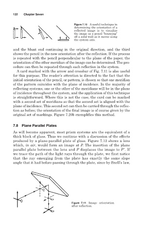
A card marked with the arrow and crossbar of Fig. 7.11 is also useful
for this purpose. The reader’s attention is directed to the fact that the
initial orientation of the pencil, or pattern, is chosen so that one meridian
of the pattern coincides with the plane of incidence. In the majority of
reflecting systems, one or the other of the meridians will be in the plane
of incidence throughout the system, and the application of this technique
is straightforward. Where this is not the case, the card can be marked
with a second set of meridians so that the second set is aligned with the
plane of incidence. This second set can then be carried through the reflec-
tion as before; the orientation of the final image is of course given by the
original set of markings. Figure 7.20b exemplifies this method.
7.8 Plane Parallel Plates
As will become apparent, most prism systems are the equivalent of a
thick block of glass. Thus we continue with a discussion of the effects
produced by a plane-parallel plate of glass. Figure 7.12 shows a lens
which, in air, would form an image at P. The insertion of the plane
parallel plate between the lens and P displaces the image to P′. If
we trace the path of the light rays through the plate, we first notice
that the ray emerging from the plate has exactly the same slope
angle that it had before passing through the plate, since by Snell’s law,
Figure 7.11 Image orientation
after reflection.