
Page 150 - Modern Optical Engineering The Design of Optical Systems
P. 150
Prism and Mirror Systems 133
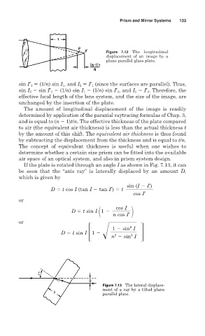
Figure 7.12 The longitudinal
displacement of an image by a
plane parallel glass plate.
sin I′ 1 (1/n) sin I 1 , and I 2 I′ 1 (since the surfaces are parallel). Thus,
sin I 2 sin I′ 1 (1/n) sin I 1 (1/n) sin I′ 2 , and I 1 I′ 2 . Therefore, the
effective focal length of the lens system, and the size of the image, are
unchanged by the insertion of the plate.
The amount of longitudinal displacement of the image is readily
determined by application of the paraxial raytracing formulas of Chap. 3,
and is equal to (n 1)t/n. The effective thickness of the plate compared
to air (the equivalent air thickness) is less than the actual thickness t
by the amount of this shift. The equivalent air thickness is thus found
by subtracting the displacement from the thickness and is equal to t/n.
The concept of equivalent thickness is useful when one wishes to
determine whether a certain size prism can be fitted into the available
air space of an optical system, and also in prism system design.
If the plate is rotated through an angle I as shown in Fig. 7.13, it can
be seen that the “axis ray” is laterally displaced by an amount D,
which is given by
sin (I I′)
D t cos I (tan I tan I′) t
cos I′
or
cos I
D t sin I 1
n cos I′
or
2
1 sin I
D t sin I 1
2
2
n sin I
Figure 7.13 The lateral displace-
ment of a ray by a tilted plane
parallel plate.