
Page 154 - Modern Optical Engineering The Design of Optical Systems
P. 154
Prism and Mirror Systems 137
Figure 7.16 “Unfolding” a 90
prism to show that it is equiva-
lent to a block of glass.
path is called a tunnel diagram. Such a diagram can be used to deter-
mine the angular field of the prism as well as the size of the beam
which will pass through the prism.
Used in this way, this prism is a constant-deviation prism.
Regardless of the angle at which a ray enters the prism, the emergent
ray will be parallel, as shown in Fig. 7.18a. This characteristic is a
property of the two reflecting surfaces of the prism. A system which
directs the light ray back on itself is called a retrodirector; this prism
is a retrodirector in one meridian only. (Another of the many constant-
deviation systems possible with two reflectors is the 90° deviation
arrangement shown in Fig. 7.18b, where the reflecting surfaces are at
45° to each other.) The constant-deviation angle is just twice the angle
between the two mirrors.
A prism made by cutting off one corner of a cube, so that there are
three mutually perpendicular reflecting surfaces, is retrodirective in
both meridians. The corner cube (or cube corner) reflector will return
all the light rays striking it back toward their source, although the
rays will be displaced laterally.
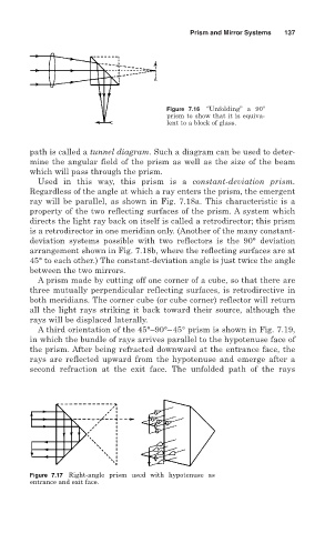
A third orientation of the 45°–90°–45° prism is shown in Fig. 7.19,
in which the bundle of rays arrives parallel to the hypotenuse face of
the prism. After being refracted downward at the entrance face, the
rays are reflected upward from the hypotenuse and emerge after a
second refraction at the exit face. The unfolded path of the rays
Figure 7.17 Right-angle prism used with hypotenuse as
entrance and exit face.