
Page 208 - Modern Optical Engineering The Design of Optical Systems
P. 208
Stops, Apertures, Pupils and Diffraction 191
Figure 9.13 Illustrating the rela-
tions between , U′, Z, l′ and w.
and to a close approximation, when is small
l′ w
Z (9.15)
n′ 2n′ sin U′
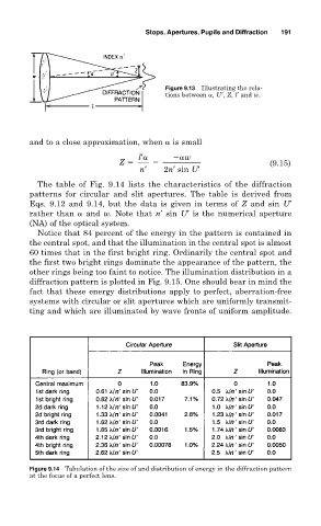
The table of Fig. 9.14 lists the characteristics of the diffraction
patterns for circular and slit apertures. The table is derived from
Eqs. 9.12 and 9.14, but the data is given in terms of Z and sin U′
rather than and w. Note that n′ sin U′ is the numerical aperture
(NA) of the optical system.
Notice that 84 percent of the energy in the pattern is contained in
the central spot, and that the illumination in the central spot is almost
60 times that in the first bright ring. Ordinarily the central spot and
the first two bright rings dominate the appearance of the pattern, the
other rings being too faint to notice. The illumination distribution in a
diffraction pattern is plotted in Fig. 9.15. One should bear in mind the
fact that these energy distributions apply to perfect, aberration-free
systems with circular or slit apertures which are uniformly transmit-
ting and which are illuminated by wave fronts of uniform amplitude.
Figure 9.14 Tabulation of the size of and distribution of energy in the diffraction pattern
at the focus of a perfect lens.