
Page 99 - Modern Optical Engineering The Design of Optical Systems
P. 99
82 Chapter Five
position, and can be expressed either directly or as a percentage of the
ideal image height, which, for an infinitely distant object, is equal to
h′ f tan .
The amount of distortion ordinarily increases as the image size
increases; the distortion itself usually increases as the cube of the
image height (percentage distortion increases as the square). Thus,
if a centered rectilinear object is imaged by a system afflicted with
distortion, it can be seen that the images of the corners will be displaced
more (in proportion) than the images of the points making up the
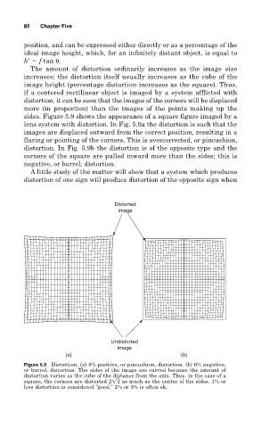
sides. Figure 5.9 shows the appearance of a square figure imaged by a
lens system with distortion. In Fig. 5.9a the distortion is such that the
images are displaced outward from the correct position, resulting in a
flaring or pointing of the corners. This is overcorrected, or pincushion,
distortion. In Fig. 5.9b the distortion is of the opposite type and the
corners of the square are pulled inward more than the sides; this is
negative, or barrel, distortion.
A little study of the matter will show that a system which produces
distortion of one sign will produce distortion of the opposite sign when
Distorted
image
Undistorted
image
(a) (b)
Figure 5.9 Distortion. (a) 8% positive, or pincushion, distortion. (b) 6% negative,
or barrel, distortion. The sides of the image are curved because the amount of
distortion varies as the cube of the distance from the axis. Thus, in the case of a
square, the corners are distorted 2 2 as much as the center of the sides. 1% or
less distortion is considered “good.” 2% or 3% is often ok.