
Page 71 - Modular design for machine tools
P. 71
Basic Knowledge: What Is the Modular Design? 41
Carriage with
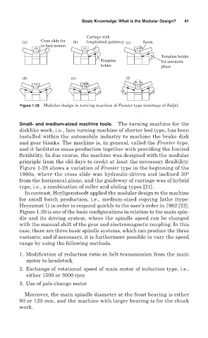
(a) Cross slide for (b) longitudinal guideway (c) Turret
in-feed motion
Template holder
Template for automatic
holder phase
(d) (e) (f)
Figure 1-28 Modular design in turning machine of Fronter type (courtesy of Saljé).
Small- and medium-sized machine tools. The turning machine for the
disklike work, i.e., face turning machine of shorter bed type, has been
installed within the automobile industry to machine the brake disk
and gear blanks. The machine is, in general, called the Fronter type,
and it facilitates mass production together with providing the limited
flexibility. In due course, the machine was designed with the modular
principle from the old days to credit at least the necessary flexibility.
Figure 1-28 shows a variation of Fronter type in the beginning of the
1960s, where the cross slide was hydraulic-driven and inclined 30°
from the horizontal plane, and the guideway of carriage was of hybrid
type, i.e., a combination of roller and sliding types [21].
In contrast, Heyligenstaedt applied the modular design to the machine
for small batch production, i.e., medium-sized copying lathe (type:
Heycomat 1) in order to respond quickly to the user’s order in 1962 [22].
Figure 1-29 is one of the basic configurations in relation to the main spin-
dle and its driving system, where the spindle speed can be changed
with the manual shift of the gear and electromagnetic coupling. In this
case, there are three basic spindle systems, which can produce the three
variants; and if necessary, it is furthermore possible to vary the speed
range by using the following methods.
1. Modification of reduction ratio in belt transmission from the main
motor to headstock
2. Exchange of rotational speed of main motor of induction type, i.e.,
either 1500 or 3000 rpm
3. Use of pole-change motor
Moreover, the main spindle diameter at the front bearing is either
90 or 120 mm, and the machine with larger bearing is for the chuck
work.