
Page 154 - Multidimensional Chromatography
P. 154
146 Multidimensional Chromatography
Figure 6.12 Schematic diagram of the interface used for direct SFE–CEST coupling
without a sample pre-concentration step: 1, micro-LC pump; 2, heated restrictor; 3, six-port
valve; 4, direct by-pass to the CE unit; 5, three-port valve; 6, CE instrument. (from ref. 58).
and the extract then concentrated in the concentrator device, while the solvent from
the SFE step was led to waste. The concentrated extract was then desorbed from the
concentrator to the CE unit where analysis was performed in the micellar electro-
kinetic chromatography (MEKC) mode. Therefore, this particular application
describes the use of an on-line SFE–MEKC coupling system. Further details con-
cerning this and other applications using such a system can be found elsewhere
(58–60).
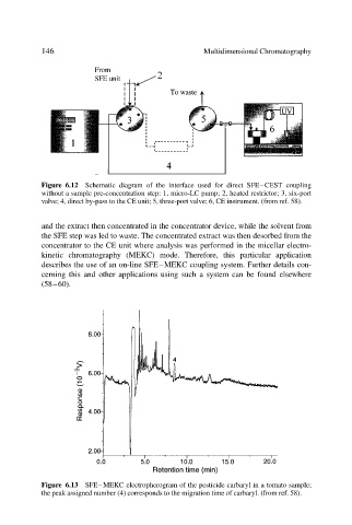
Figure 6.13 SFE–MEKC electropherogram of the pesticide carbaryl in a tomato sample;
the peak assigned number (4) corresponds to the migration time of carbaryl. (from ref. 58).