
Page 153 - Multidimensional Chromatography
P. 153
Coupled Supercritical Fluid and Chromatographic Techniques 145
Figure 6.10 Schematic diagram of a typical interface used for on-line SFE–CEST
coupling (from ref. 57): 1, micro-LC pump; 2, heated restrictor; 3, six-port valve; 4, sample
concentrator; 5, three-port valve; 6, CE instrument.
analytes of interest are concentrated in the cartridge, the solvent is vented through
the valve (item (5) in Figure 6.10). Upon completing the concentration step, the
valves are then switched to the elution position (Figure 6.11(b), and a pump delivers
the appropriate solvent to elute the sample from the SPE cartridge to the CE vial.
After this step, the CE analysis is then carried out.
The direct mode is used when the concentration of the SFE extract is enough for
direct analysis in the CE instrument without the need for a pre-concentration step. In
this case, the sample concentrator is by-passed and the SFE extract goes directly to
the CE instrument. The extract is collected in a CE vial containing an appropriate
solvent and is thus ready for the CE analysis (Figure 6.12).
A practical application of SFE–CEST coupling is shown in Figure 6.13, which
displays the electropherogram obtained for a tomato sample contaminated with a
pesticide, i.e. carbaryl. The sample was placed in the SFE cell, extracted with CO 2
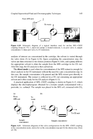
Figure 6.11 Schematic diagrams of the valve configurations for the SFE–CEST coupling
in the concentration mode, shown for (a) the concentration step and (b) the elution step. (from
ref. 58)