
Page 152 - Multidimensional Chromatography
P. 152
144 Multidimensional Chromatography
electrokinetic chromatography (MEKC) and, more recently, capillary electrochro-
matography (CEC) (48–52). All capillary electrodriven separation techniques
(CESTs) suffer from the same problem, i.e. the low detection sensitivity due to the
use of narrow capillaries which are required in order to achieve the desired efficiency
and prevent an excess of heating due to the Joule effect (53, 54). One way to over-
come this limitation has been the use of membranes, cartridges, hollow fibers and
similar approaches to concentrate the analytes prior to the electrophoretic separation
(55–57). A more general approach that can overcome this problem, as well as to
provide additional features, particularly for the analysis of complex real samples,
involves the on-line coupling of supercritical fluid extraction and capillary electro-
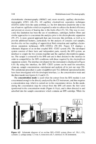
driven separation techniques (SFE–CESTs) (58–60). Figure 6.9 displays a
schematic diagram of an on-line coupled SFE–CEST system (58). The developed
system consists of three basic and independent parts, namely the SFE system, an
interface to couple the two systems together and the capillary electrodriven appara-
tus. The sample is extracted in the SFE unit and is then directed to the interface in
order to compatibilize the SFE conditions with those required by the electrodriven
separation system. The interface developed for this instrument is displayed in Figure
6.10. By using this interface, the SFE–CEST system can be used for extraction,
clean-up, sample concentration–enrichment and analysis all in just one step (58).
The operational procedure is quite straightforward. Two different operational modes
have been investigated with the developed interface, i.e. the concentration mode and
the direct mode (see figures 6.11 and 6.12).
The concentration mode is used when the extract from the SFE module is not
concentrated enough to be directly analyzed by the CE instrument, and thus requires
a concentration step, which is carried out in the concentrator device. In this mode,
during the concentration step the extract from the SFE cell enters the first valve
(positioned in the concentration mode (Figure 6.11(a)), and is then directed to and
adsorbed into the sample concentrator which contains an SPE cartridge. While the
Figure 6.9 Schematic diagram of an on-line SFE–CEST system (from ref. 58):1, CO 2
cylinder; 2, syringe pump; 3, oven; 4, extraction cell; 5, interface; 6, CE instrument.