
Page 91 - Multidimensional Chromatography
P. 91
Orthogonal GC–GC 83
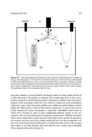
Figure 4.3 Schematic diagram of a thermal sweeper system located between two columns in
the gas chromatograph; C1, C2 and C3 are column connections, with C2 being small enough
to allow the slotted heater S to pass over the connection. The accumulator column A retards
the travel of solutes through this section until the sweeper expels them out to the uncoated col-
umn (called a pigtail (P)), which then delivers them as a narrow band to the second column.
The modulation drive, M, is external to the GC oven.
along the column as a focused band as the heater rotates over the column section. It
is then delivered to 2D quickly, as required. The sweeper may have to pass over a
column connection, and this had presented a robustness problem in the early devel-
opment of the technology. Often the first column is connected to the accumulator
column by using a short uncoated capillary, and another uncoated column is placed
before 2D. This involves a total of four column connections. A more recent version
of the commercial system incorporates a separately controllable heater block in
which 2D is located in order to allow independent thermal control of the two
columns. This may aid optimization of separation performance. Whether the heated
block causes temperature control concerns in the main oven is unclear. In operation,
the sweeper arm runs across the column section and sits over the accumulator col-
umn exit connection to ensure full transfer of solute out of that section. The sweeper
then rotates to its home position and waits until the next sweep event is initiated.
These steps are indicated on Figure 4.4.