
Page 204 - Book Hosokawa Nanoparticle Technology Handbook
P. 204
FUNDAMENTALS CH. 4 CONTROL OF NANOSTRUCTURE OF MATERIALS
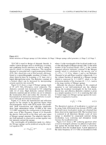
Figure 4.2.1
Model structures of Menger sponge (a) Cube initiator; (b) Stage 1 Menger sponge called generator; (c) Stage 2; (d) Stage 3.
3D-CAD is used to design of photonic fractals. It where is the wavelength of the localized mode in air,
enables various designs such as modifying, reversing, a is the side length of Menger sponge cube, l is the order
and combining fractal structures as well as cutting at number of the localized modes, and is the volume
eff
specific planes or joining connectors. The designed averaged effective dielectric constant of the Menger
structure is converted into a rapid prototyping format sponge which is calculated by the mixing rule of
(STL file), sliced into a set of thin sections, and trans- V (1–V ) , where and are dielectric
A
eff
B
B
f
f A
ferred to a stereolithographic machine. It forms a 3D constants of air and object material, respectively. V is
f
object layer-by-layer by scanning a UV laser over a the volume fraction of material in a Menger sponge
liquid photopolymer resin. The dielectric constant of which is expressed by V (N/S ) , where n is the
n m
f
a formed object can be increased by incorporating dimension number of the structure (0, 1 ,2 ,3...) and m
ceramic particles into resin [8]. is the stage number of Menger sponge.
Figure 4.2.2 shows a stage 4 Menger sponge made Although the physical meaning of this empirical
of 10 vol% TiO –SiO /epoxy resin composite. The equation is not well-understood yet, the relation
2
2
dielectric constant was increased to 8.8 comparing among the localized wavelength for the first mode,
with 2.8 of resin. High dielectric contrast between fractal size, and effective dielectric constant is given
dielectric material and air cavities can act to enhance as a simple equation (4.2.3). It is surprising that only
the localization effect and reduce the structure size. 1.5 times larger size Menger sponge against the wave-
Incorporation of nanosized ceramic particles is essen- length is required to localize.
tial to fabricate microfractal structures.
Figure 4.2.3 shows the transmission and reflection 23a (4.2.3)
spectra for the sample in the previous figure when eff
electromagnetic waves with TE10 mode were irradi-
ated. Both transmission and reflection amplitudes The theoretical analysis of localization is carried out
show large attenuations below 1/1,000 at the same by using finite differential time domain (FDTD) code
13.5 GHz suggesting the confinement of electromag- and much more localization modes are obtained than
netic wave at this frequency. Figure 4.2.4 illustrates those observed in experiment [10]. The localized wave
the electric field profile at the inner and outer space is scattered to all directions though a part of wave
of Menger sponge structure. The relatively high elec- energy is absorbed by component material during
tric field intensity is observed in cavities against very localization. Less scattering and absorption would
low intensity around the sponge. increase the localization time.
The wavelengths of localization mode in a dielec- Figure 4.2.5 shows a 90 scattering spectrum when
tric Menger sponge can be predicted using the empir- a receiver monopole antenna was placed at right direc-
ical equation [9]: tion against the incident beam in order to avoid the
influence from the incident beam. A peak appeared at
l
2 a eff 3 2l 1 (4.2.2) the same frequency of 13.5 GHz as measured in both
180