
Page 38 - Neural Network Modeling and Identification of Dynamical Systems
P. 38
26 1. THE MODELING PROBLEM FOR CONTROLLED MOTION OF NONLINEAR DYNAMICAL SYSTEMS
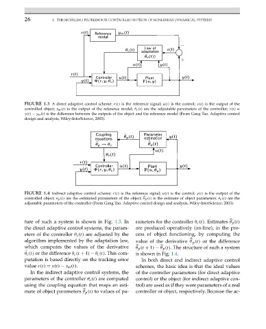
FIGURE 1.3 A direct adaptive control scheme: r(t) is the reference signal; u(t) is the control; y(t) is the output of the
controlled object; y m (t) is the output of the reference model; θ c (t) are the adjustable parameters of the controller; ε(t) =
y(t) − y m (t) is the difference between the outputs of the object and the reference model (From Gang Tao. Adaptive control
design and analysis, Wiley-InterScience, 2003).
FIGURE 1.4 Indirect adaptive control scheme: r(t) is the reference signal; u(t) is the control; y(t) is the output of the
controlled object; θ p (t) are the estimated parameters of the object; θ p (t) is the estimate of object parameters; θ c (t) are the
adjustable parameters of the controller (From Gang Tao. Adaptive control design and analysis, Wiley-InterScience, 2003).
ture of such a system is shown in Fig. 1.3.In rameters for the controller θ c (t). Estimates θ p (t)
the direct adaptive control systems, the param- are produced operatively (on-line), in the pro-
eters of the controller θ c (t) are adjusted by the cess of object functioning, by computing the
˙
algorithm implemented by the adaptation law, value of the derivative θ p (t) or the difference
which computes the values of the derivative θ p (t + 1) − θ p (t). The structure of such a system
˙ (t) or the difference θ c (t + 1) − θ c (t).Thiscom-
θ c is shown in Fig. 1.4.
putation is based directly on the tracking error In both direct and indirect adaptive control
value ε(t) = y(t) − y m (t). schemes, the basic idea is that the ideal values
In the indirect adaptive control systems, the of the controller parameters (for direct adaptive
parameters of the controller θ c (t) are computed control) or the object (for indirect adaptive con-
using the coupling equation that maps an esti- trol) are used as if they were parameters of a real
mate of object parameters θ p (t) to values of pa- controller or object, respectively. Because the ac-