
Page 26 - Numerical Analysis and Modelling in Geomechanics
P. 26
SURFACE DISPLACEMENTS OF AN AIRFIELD RUNWAY 7
consider the effect of increasing the depth of detonation on the surface deflection
of the runway. For this determination the depth was increased in steps by 1 m, 2
m, 3 m, 4 m, 7 m and 10 m. It was considered that the position of the zone 1–8
interface did not change and hence the cone apex angle would reduce as the
camouflet depth increased. As the depth of the camouflet increases to 9.354 m,
10.354 m, 11.354 m, 12.354 m, 15.354 m and 18.354 m, the cone apex angle
changes to 86.58°, 80.8°, 75.62°, 71.0°, 59.7°and 51.28° respectively.
As there is no other published research that details the changes in the subgrade
cone above a camouflet detonation, this research considers the 17 material sets
shown in Table 1.1, by changing the Young’s modulus of only zones 2, 3, 4, 5
and 6 in Figure 1.1. These material sets cover a range of subgrade possibilities,
between material set 1 where zones 2, 3, 4 and 5 are all increased in strength to
material set 17 where zones 2, 3, 4 and 5 are all reduced in strength.
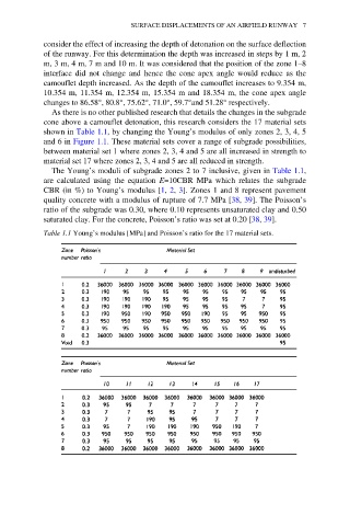
The Young’s moduli of subgrade zones 2 to 7 inclusive, given in Table 1.1,
are calculated using the equation E=10CBR MPa which relates the subgrade
CBR (in %) to Young’s modulus [1, 2, 3]. Zones 1 and 8 represent pavement
quality concrete with a modulus of rupture of 7.7 MPa [38, 39]. The Poisson’s
ratio of the subgrade was 0.30, where 0.10 represents unsaturated clay and 0.50
saturated clay. For the concrete, Poisson’s ratio was set at 0.20 [38, 39].
Table 1.1 Young’s modulus [MPa] and Poisson’s ratio for the 17 material sets.