
Page 29 - Numerical Analysis and Modelling in Geomechanics
P. 29
10 JOHN W.BULL AND C.H.WOODFORD
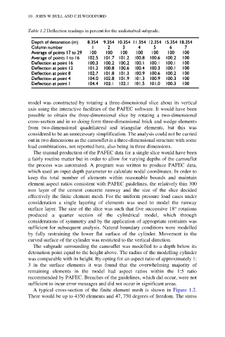
Table 1.2 Deflection readings in percent for the undisturbed subgrade.
model was constructed by rotating a three-dimensional slice about its vertical
axis using the interactive facilities of the PAFEC software. It would have been
possible to obtain the three-dimensional slice by rotating a two-dimensional
cross-section and in so doing form three-dimensional brick and wedge elements
from two-dimensional quadrilateral and triangular elements, but this was
considered to be an unnecessary simplification. The analysis could not be carried
out in two dimensions as the camouflet is a three-dimensional structure with some
load combinations, not reported here, also being in three dimensions.
The manual production of the PAFEC data for a single slice would have been
a fairly routine matter but in order to allow for varying depths of the camouflet
the process was automated. A program was written to produce PAFEC data,
which used an input depth parameter to calculate nodal coordinates. In order to
keep the total number of elements within reasonable bounds and maintain
element aspect ratios consistent with PAFEC guidelines, the relatively thin 300
mm layer of the cement concrete runway and the size of the slice decided
effectively the finite element mesh. For the uniform pressure load cases under
consideration a single layering of elements was used to model the runway
surface layer. The size of the slice was such that five successive 18° rotations
produced a quarter section of the cylindrical model, which through
considerations of symmetry and by the application of appropriate restraints was
sufficient for subsequent analysis. Natural boundary conditions were modelled
by fully restraining the lower flat surface of the cylinder. Movement in the
curved surface of the cylinder was restricted to the vertical direction.
The subgrade surrounding the camouflet was modelled to a depth below its
detonation point equal to the height above. The radius of the modelling cylinder
was comparable with its height. By opting for an aspect ratio of approximately 1:
3 in the surface elements it was found that the overwhelming majority of
remaining elements in the model had aspect ratios within the 1:5 ratio
recommended by PAFEC. Breaches of the guidelines, which did occur, were not
sufficient to incur error messages and did not occur in significant areas.
A typical cross-section of the finite element mesh is shown in Figure 1.2.
There would be up to 4350 elements and 47, 750 degrees of freedom. The stress