
Page 32 - Numerical Analysis and Modelling in Geomechanics
P. 32
SURFACE DISPLACEMENTS OF AN AIRFIELD RUNWAY 13
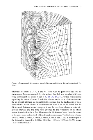
Figure 1.3 A quarter finite element model of the camouflet for a detonation depth of 12.,
354m.
thickness of zones 2, 3, 4, 5 and 6. There was no published data on the
phenomena. Previous research by the authors had led to a standard thickness
being determined for zones 5 and 6 [8, 14, 16, 17, 34]. Further consideration
regarding the extent of zones 3 and 4 in relation to the point of detonation and
the air-ground interface led the authors to conclude that the thicknesses of these
zones should not be altered. Consideration of zone 2 led to the belief that the
thickness of that zone would change as it was the zone located nearest to the air-
ground interface and the zone most effected by the reflections of the shock
waves from that interface. For this reason the thickness of zone 2 was increased
in the same steps as the depth of the detonation increased. The thickness of zone
2 was 2.753 m, 3.753 m, 4.753 m, 5.753 m, 8.753 m and 11.753 m as the depth of
the detonation changed to 9.354m, 10.354m, 11.354m, 12.354m, 15.354 m and
18.354 m respectively.