
Page 31 - Numerical Analysis and Modelling in Geomechanics
P. 31
12 JOHN W.BULL AND C.H.WOODFORD
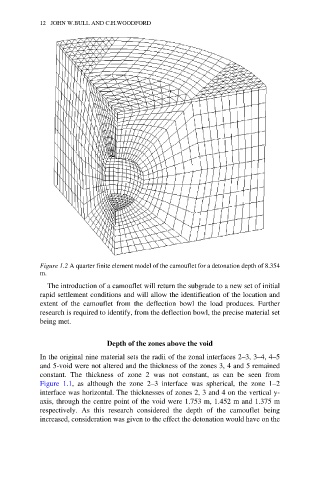
Figure 1.2 A quarter finite element model of the camouflet for a detonation depth of 8.354
m.
The introduction of a camouflet will return the subgrade to a new set of initial
rapid settlement conditions and will allow the identification of the location and
extent of the camouflet from the deflection bowl the load produces. Further
research is required to identify, from the deflection bowl, the precise material set
being met.
Depth of the zones above the void
In the original nine material sets the radii of the zonal interfaces 2–3, 3–4, 4–5
and 5-void were not altered and the thickness of the zones 3, 4 and 5 remained
constant. The thickness of zone 2 was not constant, as can be seen from
Figure 1.1, as although the zone 2–3 interface was spherical, the zone 1–2
interface was horizontal. The thicknesses of zones 2, 3 and 4 on the vertical y-
axis, through the centre point of the void were 1.753 m, 1.452 m and 1.375 m
respectively. As this research considered the depth of the camouflet being
increased, consideration was given to the effect the detonation would have on the