
Page 321 - Numerical Analysis and Modelling in Geomechanics
P. 321
302 ANALYSIS AND DESIGN OF PILE GROUPS
Table 10.5 Additional parameters for the non-linear analyses reported in Figures 10.6–10.
7
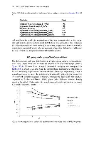
soil non-linearity results in a reduction of the load concentration at the corner
pile and hence a more uniform load distribution. The amount of this reduction
will depend on the load level. Finally, it should be emphasised that the numerical
simulations presented herein take no account of possible failure by yielding of
the pile section, i.e. the pile is assumed to remain elastic.
Pile group under general loading conditions
The deformations and load distribution in a 3-pile group under a combination of
axial load, lateral load and moment are examined in the linear range (refer to
Figure 10.8). Results from selected numerical analyses are compared in
Table 10.6 in which w , u and θ are the vertical head displacement of pile no. 3,
3
the horizontal cap displacement and the rotation of the cap, respectively. There is
a good agreement between the solutions which consider pile-soil-pile interaction
(even if with different degrees of rigour), whereas the equivalent-bent analysis
(reported in Poulos and Davis, 1980) gives quite different results, thereby
showing the pitfall of attempting to model a complex pile-soil system by means
of a simple structural frame.
Figure 10.7 Comparison of lateral load distribution to individual piles in 5×5 pile group.