
Page 378 - Numerical Analysis and Modelling in Geomechanics
P. 378
RESERVOIR COMPACTION, SUBSIDENCE AND WELL DAMAGE 359
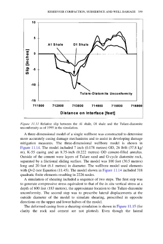
Figure 11.11 Relative slip between the Al shale, Dl shale and the Tulare-diatomite
unconformity as of 1995 in the simulation.
A three-dimensional model of a single wellbore was constructed to determine
more accurately casing damage mechanisms and to assist in developing damage
mitigation measures. The three-dimensional wellbore model is shown in
Figure 11.14. The model included 7 inch (0.178 metres) OD, 26 lb/ft (37.8 kg/
m), K-55 casing and an 8.75-inch (0.222 metres) OD cement-filled annulus.
Outside of the cement were layers of Tulare sand and G-cycle diatomite rock,
separated by a frictional sliding surface. The model was 100 feet (30.5 metres)
long and 20 feet (6.1 metres) in diameter. The wellbore model used elements
with Q=2 (see Equation (11.45). The model shown in Figure 11.14 included 318
quadratic finite elements resulting in 2226 nodes.
A simulation of shearing included a sequence of two steps. The first step was
to generate compressive stress equivalent to that of the in situ vertical stress at a
depth of 600 feet (183 metres), the approximate location to the Tulare-diatomite
unconformity. The second step was to prescribe lateral displacements at the
outside diameter of the model to simulate shearing, prescribed in opposite
directions on the upper and lower halves of the model.
The deformed casing from a shearing simulation is shown in Figure 11.15 (for
clarity the rock and cement are not plotted). Even though the lateral