
Page 383 - Numerical Analysis and Modelling in Geomechanics
P. 383
364 RESERVOIR COMPACTION, SUBSIDENCE AND WELL DAMAGE
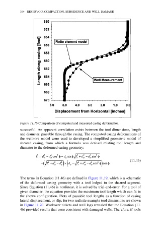
Figure 11.16 Comparison of computed and measured casing deformation.
successful. An apparent correlation exists between the tool dimensions, length
and diameter, passable through the casing. The computed casing deformations of
the wellbore model were used to developed a simplified geometric model of
sheared casing, from which a formula was derived relating tool length and
diameter to the deformed casing geometry:
(11.46)
The terms in Equation (11.46) are defined in Figure 11.19, which is a schematic
of the deformed casing geometry with a tool lodged in the sheared segment.
Since Equation (11.46) is nonlinear, it is solved by trial-and-error. For a tool of
given diameter, the equation provides the maximum tool length which can fit in
the shown configuration. Plots of passable tool lengths as a function of casing
lateral displacement, or slip, for two realistic example tool dimensions are shown
in Figure 11.20. Workover tickets and well logs revealed that the Equation (11.
46) provided results that were consistent with damaged wells. Therefore, if tools