
Page 384 - Numerical Analysis and Modelling in Geomechanics
P. 384
RESERVOIR COMPACTION, SUBSIDENCE AND WELL DAMAGE 365
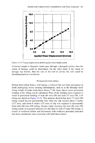
Figure 11.17 Casing displacement plotted against shear displacement.
of known length or diameter cannot pass through a damaged section, then the
extent of damage could be determined. On the other hand, if the extent of
damage was known, then the size of the tool to service the well could be
determined prior to a workover.
Permanently bent tubing
Pulling bent tubing from a well during a workover has not been uncommon in
fields undergoing severe shearing deformations, such as in the Belridge field.
Using simple formulas from beam theory, 96 the shear slip to cause permanent
bending of the tubing can be calculated. Plots of the bending stress required to
result in permanent bending of inch (60 mm) OD and inch (73 mm) OD, J-55
tubing are shown in Figure 11.21. This analysis showed that inch (73 mm) OD
tubing would become permanently bent when the slip reached about 5 inches
(127 mm), and about 6 inches (152 mm) of slip was required to permanently
bend inch (60 mm) OD tubing. Greater radial clearance for inch (60 mm) OD
tubing results in its greater tolerance for slip than for inch (73 mm) OD tubing. A
review of workover tickets and discussions with workover personnel indicated
that these calculations were consistent with field observations.