
Page 90 - Numerical Analysis and Modelling in Geomechanics
P. 90
WAVE-SEABED-STRUCTURE INTERACTION 71
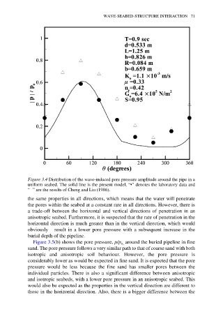
Figure 3.4 Distribution of the wave-induced pore pressure amplitude around the pipe in a
uniform seabed. The solid line is the present model, “•” denotes the laboratory data and
“≥ ” are the results of Cheng and Liu (1986).
the same properties in all directions, which means that the water will penetrate
the pores within the seabed at a constant rate in all directions. However, there is
a trade-off between the horizontal and vertical directions of penetration in an
anisotropic seabed. Furthermore, it is suspected that the rate of penetration in the
horizontal direction is much greater than in the vertical direction, which would
obviously result in a lower pore pressure with a subsequent increase in the
burial depth of the pipeline.
Figure 3.5(b) shows the pore pressure, p/p around the buried pipeline in fine
o,
sand. The pore pressure follows a very similar path to that of coarse sand with both
isotropic and anisotropic soil behaviour. However, the pore pressure is
considerably lower as would be expected in fine sand. It is expected that the pore
pressure would be less because the fine sand has smaller pores between the
individual particles. There is also a significant difference between anisotropic
and isotropic seabeds, with a lower pore pressure in an anisotropic seabed. This
would also be expected as the properties in the vertical direction are different to
those in the horizontal direction. Also, there is a bigger difference between the