
Page 200 - Offshore Electrical Engineering Manual
P. 200
Technical Organisation of the Design Programme 187
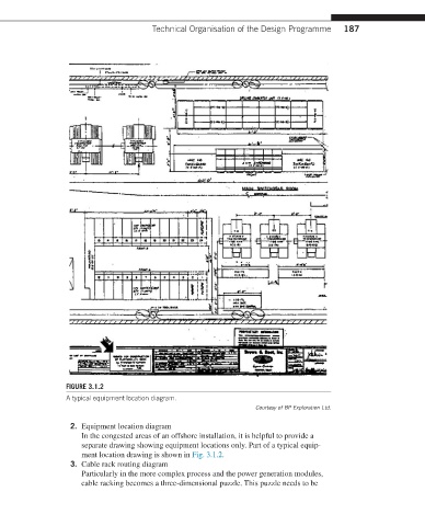
FIGURE 3.1.2
A typical equipment location diagram.
Courtesy of BP Exploration Ltd.
2. Equipment location diagram
In the congested areas of an offshore installation, it is helpful to provide a
separate drawing showing equipment locations only. Part of a typical equip-
ment location drawing is shown in Fig. 3.1.2.
3. Cable rack routing diagram
Particularly in the more complex process and the power generation modules,
cable racking becomes a three-dimensional puzzle. This puzzle needs to be