
Page 363 - Offshore Electrical Engineering Manual
P. 363
350 CHAPTER 2 Generators
temporary means of preventing rotation. The start permissive key should be
removed from the prime mover control panel. Having made certain that every-
thing is electrically and mechanically safe, work can then begin on testing the
generator windings.
3. Cold resistance of main stator windings
The method involves injecting a known direct current through each winding
and measuring the voltage drop through the winding at the terminals. Before
applying the current, the earth must be removed from the winding. Readings
of voltage and current should be recorded for all three phases. The three
resistances calculated from these readings after compensating for ambient
temperature should not deviate from each other by more than 2% or from the
manufacturer’s design figure by more than 5%. For compensation purposes,
the ambient air temperature will need to be measured at shaft height and 1 m
from the alternator frame.
4. Rotor and exciter field windings
The resistance of these windings should be measured in the same way as the
stator windings. Using an alternating current high-voltage test unit, the genera-
tor windings should be tested to twice their working voltage plus 1000 V, with
a minimum of 1500 V as required in BS 4999. The windings should withstand
this voltage for 1 min. The voltage should be gradually applied, and the minute
count started once full test voltage has been reached.
5. Exciter
The exciter field should be tested in the same way and using the same criteria
after temporarily removing the AVR connections. With a brushless machine,
the rotor and exciter armature should be checked for continuity only, in order
to avoid damage to the diode bridge.
6. Anticondensation heaters
Anticondensation heaters should be high voltage tested to about 1500 V to the
machine frame, with adjacent windings earthed. A continuity check should
also be carried out.
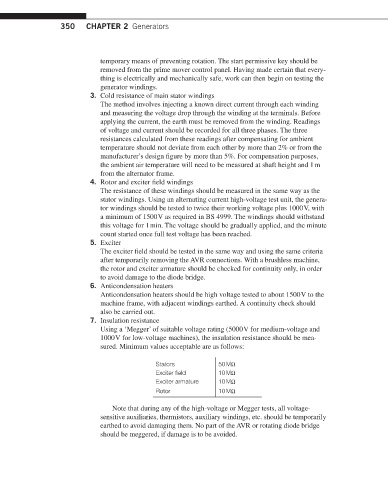
7. Insulation resistance
Using a ‘Megger’ of suitable voltage rating (5000 V for medium-voltage and
1000 V for low-voltage machines), the insulation resistance should be mea-
sured. Minimum values acceptable are as follows:
Stators 50 MΩ
Exciter field 10 MΩ
Exciter armature 10 MΩ
Rotor 10 MΩ
Note that during any of the high-voltage or Megger tests, all voltage-
sensitive auxiliaries, thermistors, auxiliary windings, etc. should be temporarily
earthed to avoid damaging them. No part of the AVR or rotating diode bridge
should be meggered, if damage is to be avoided.