
Page 367 - Offshore Electrical Engineering Manual
P. 367
354 CHAPTER 3 Switchgear
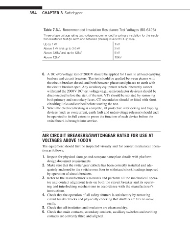
Table 7.3.1 Recommended Insulation Resistance Test Voltages (BS 6423)
Three-phase voltage rating test voltage recommended for primary insulation for the insula-
tion resistance test (to earth and between phases) in kilovolt DC (1 min)
Up to 1 kV 1 kV
Above 1 kV and up to 3.6 kV 2 kV
Above 3.6 kV and up to 12 kV 5 kV
Above 12 kV 10 kV
6. A DC overvoltage test of 2000 V should be applied for 1 min to all load-carrying
busbars and circuit breakers. The test should be applied between phases with
the circuit breaker closed, and both between phases and phases-to-earth with
the circuit breaker open. Any auxiliary equipment which inherently cannot
withstand the 2000 V DC test voltage (e.g., semiconductor devices) should be
disconnected before the start of the test. VTs should be isolated by removing
both primary and secondary fuses. CT secondaries should be fitted with short-
circuiting links and earthed before starting the test.
7. When the electrical testing is complete, all protective interlocking and tripping
devices (such as overcurrent, earth fault and undervoltage releases) should each
be operated to its full extent to prove the function of each device before the
switchboard is brought into service.
AIR CIRCUIT BREAKERS/SWITCHGEAR RATED FOR USE AT
VOLTAGES ABOVE 1000 V
The equipment should first be inspected visually and for correct mechanical opera-
tion as follows:
1. Inspect for physical damage and compare nameplate details with platform
design document requirements.
2. Make sure that the switchgear cubicle has been correctly installed and ade-
quately anchored to the switchroom floor to withstand shock loadings imposed
by operation of circuit breakers.
3. Refer to the manufacturer’s manuals and perform all the mechanical opera-
tor and contact alignment tests on both the circuit breaker and its operat-
ing and interlocking mechanisms in accordance with the manufacturer’s
instructions.
4. Check that the operation of all safety shutters is satisfactory by removing
circuit breaker trucks and physically checking that shutters are free to move
easily.
5. Check that all insulation and insulators are clean and dry.
6. Check that main contacts, secondary contacts, auxiliary switches and earthing
contacts are correctly fitted and aligned.