
Page 368 - Offshore Electrical Engineering Manual
P. 368
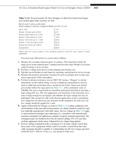
Air Circuit Breakers/Switchgear Rated for Use at Voltages Above 1000 V  355


                   Table 7.3.2  Recommended DC Test Voltages on Metal-Enclosed Switchgear
                   and Control gear After Erection on Site
                   (BS EN 62271-200 and BS 6423)
                   Rated voltage (U) site test voltage (kV RMS) in kV DC (15 min)
                   Up to 1 kV                       1 kV
                   Above 1 kV and up to 3.6 kV      2 kV
                   Above 3.6 kV and up to 7.2 kV    7.5 kV
                   Above 7.2 kV and up to 12 kV     15 kV
                   Above 12 kV and up to 17.5 kV    25 kV
                   Above 17.5 kV and up to 24 kV    32 kV
                   Above 24 kV and up to 36 kV      45 kV
                   Above 36 kV                      66 kV

                   Please check the current versions of the standards quoted to verify the correct values of these
                   parameters.
                     Electrical tests will need to be carried out as follows:

                    1.   Measure the resistance between pairs of contacts. This should be within the
                     range given in the manufacturer’s manual and not more than 500 μΩ if excessive
                     contact heating is to be avoided.
                    2.   Perform a voltage pick-up test on the tripping and closing coils.
                    3.   Trip the circuit breaker several times by operating each protective device in turn.
                    4.   Measure the primary insulation resistance for pole-to-ground, pole-to-pole and
                     across open poles of the same phase.
                    5.   Perform insulation resistance tests at 500 V DC (using a ‘Megger’ or similar
                     instrument) on all control wiring. Circuits containing semiconductor devices,
                     such as solid-state protection relays, should not be tested. These tests should
                     give results within the range given in Table 7.3.1, with a minimum value of
                     100 MΩ. The above-mentioned test should be performed both before and after a
                     high-voltage DC test. The first application will determine if the insulation resis-
                     tance is high enough for acceptance and whether the high-voltage test may be
                     performed. The second test will verify that the application of the overpotential
                     test voltage has not shown up any weakness in the insulation. In each case, the
                     test voltage should be applied for 1 min.
                    6.   Apply overpotential test voltages, as shown in Table 7.3.2, to phase conductors with
                     circuit breakers in the open and closed positions. Arc chutes should be tested for watts
                     loss within the manufacturer’s allowable values. The test voltages in Table 7.3.2 apply
                     to metal-enclosed switchgear and control gear (i.e., assemblies with external metal
                     enclosures intended to be earthed and complete except for external connections). The
                     switchgear under test should be free from all external cabling, VTs, CTs and other
                     auxiliary equipment which cannot withstand the test voltage being applied.
                    7.   If main cabling terminated at the switchgear is to be high voltage tested, then
                     those parts of the equipment which cannot be readily isolated from the main
                     cable terminals should be capable of withstanding the DC test voltage specified
                     in BS EN 62271-200 for 15 min (i.e., the duration of the test).