
Page 46 - Offshore Electrical Engineering Manual
P. 46
Thermal Overloads and Motor Thermal Protection 33
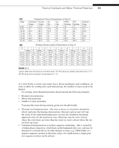
(A) Temperature Probes [Temperatures in Deg C]
Time Alternator Exciter Air Air ND/E D/E Ambient
Frame Frame Out Out Bearing Bearing Temp.
8:30 17.5 17.5 17 19 18 17 16.75
9:30 37 36.5 19.5 30 33 35.5 19.5
10:30 43.5 41.5 21.5 33 37.5 44 21.25
11:30 46 43.5 23 35 39 47 22
12:30 47.5 44.5 21 35 40 50 21.25
13:30 46.5 43.5 21 34 38.5 49 21.5
14:30 46.5 43.5 21 34 38.5 48.5 21.5
(B) Winding Thermocouples [Temperatures in Deg C]
°C 1 1 2 2 3 3 4 4 5 5 6 6
Ohms °C Ohms °C Ohms °C Ohms °C Ohms °C Ohms °C
08:30 105.42 11.5 105.37 11.5 105.61 12 105.32 11 105.45 11.5 105.38 11.5
09:30 129.2 75.5 133.54 87 130.6 79.5 130.9 80 132.6 79.5 128.2 73
10:30 132.5 84 136 93.5 134.45 89.5 134.6 89.5 135.8 93 132.5 84
11:30 124.6 89 137.7 98 135.7 92.5 136.2 94 137.7 98 132.6 84.5
12:30 134.6 89 138.3 99.5 135.8 93 136.3 94 137.9 98.5 132.8 85
13:30 134.15 88.5 137.9 98.5 135.4 92 135.9 93 137.6 98 132.75 85
14:30 134.15 88.5 137.9 98.5 135.5 92 135.9 93 137.6 97.5 132.3 83.5
FIGURE 2.1.1
Typical alternator temperature rise test result. (A) Temperature probes (temperatures in °C).
(B) Winding thermocouples (temperatures in °C).
of a rotor block or motor start under heavy driven-machinery load conditions. In
order to allow for cooling after each load attempt, the number of starts needs to be
limited.
For starting, motor thermal protection should include the following elements:
• Blocked rotor protection
• Motor start protection
• Number of starts protection
To protect the motor during running, protection should include:
• Thermal overload protection – this uses a device or electronic simulation
which replicates the heating characteristic (thermal replica) and will trip
the motor if the replicated temperature exceeds the insulation maximum
approved value for the insulation class. Machines may be rotor critical,
where the rotor heats up faster than the stator or stator critical where the sta-
tor heats up faster.
• Unbalanced load protection or positive sequence monitoring – this is caused by
a broken phase connection, which heats up the laminated rotor core, and may be
detected by a bimetal device (in older designs of relays, e.g., P&B Golds) or a
negative sequence monitor in electronic relays. For small motors a simple posi-
tive sequence monitor can be utilised.