
Page 49 - Offshore Electrical Engineering Manual
P. 49
36 CHAPTER 2 AC Synchronous Generators
(A) E (B) E (C) E
δ jI X
δ V jI X δ V jI X θ V A S
A S
A S
θ I R I A I R I A I R
A A
A A
A A
I A
Lagging Power Factor Unity Power Factor Leading Power Factor
Phasor Diagram Phasor Diagram Phasor Diagram
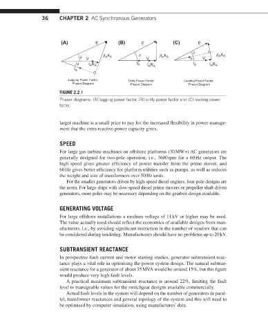
FIGURE 2.2.1
Phasor diagrams: (A) lagging power factor, (B) unity power factor and (C) leading power
factor.
larger machine is a small price to pay for the increased flexibility in power manage-
ment that the extra reactive power capacity gives.
SPEED
For large gas turbine machines on offshore platforms (30 MW+) AC generators are
generally designed for two-pole operation, i.e., 3600 rpm for a 60 Hz output. The
high speed gives greater efficiency of power transfer from the prime mover, and
60 Hz gives better efficiency for platform utilities such as pumps, as well as reduces
the weight and size of transformers over 50 Hz units.
For the smaller generators driven by high-speed diesel engines, four-pole designs are
the norm. For large ships with slow-speed diesel prime movers or propeller shaft driven
generators, more poles may be necessary depending on the gearbox design available.
GENERATING VOLTAGE
For large offshore installations a medium voltage of 11 kV or higher may be used.
The value actually used should reflect the economics of available designs from man-
ufacturers, i.e., by avoiding significant restriction in the number of vendors that can
be considered during tendering. Manufacturers should have no problems up to 20 kV.
SUBTRANSIENT REACTANCE
In prospective fault current and motor starting studies, generator subtransient reac-
tance plays a vital role in optimising the power system design. The natural subtran-
sient reactance for a generator of about 35 MVA would be around 15%, but this figure
would produce very high fault levels.
A practical maximum subtransient reactance is around 22%, limiting the fault
level to manageable values for the switchgear designs available commercially.
Actual fault levels in the system will depend on the number of generators in paral-
lel, transformer reactances and general topology of the system and this will need to
be optimised by computer simulation, using manufactures’ data.