
Page 53 - Offshore Electrical Engineering Manual
P. 53
40 CHAPTER 2 AC Synchronous Generators
0.8
r Field heating limit
0.7
0.8 PF
0.6
Into the system (overexcited) 0.5 m 0.9 PF
0.4
0.95 PF
0.3 Armature
heating
limit
0.2
k
Per-unit megavars Q o 0.0 0.1 θ 0.2 0.3 0.4 0.5 0.6 0.7 0.8 0.9 p 1.0 PF
0.1
+
1.0
–
Per-unit megawatts P
Prime
0.1
mover
limit
0.2
100% excitation circle
0.3 0.95 PF
From the system (underexcited) 0.4 δ Underexcitation limit m’ 0.90 PF
0.5
0.58
0.6 n
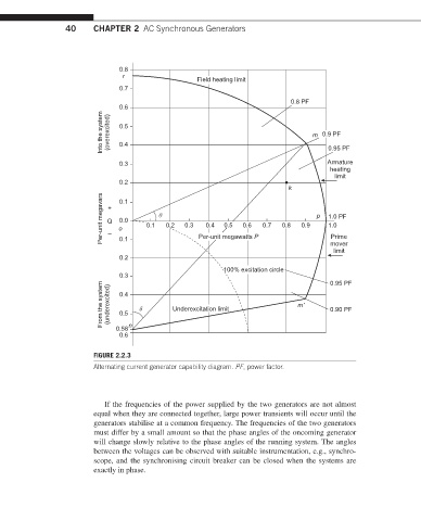
FIGURE 2.2.3
Alternating current generator capability diagram. PF, power factor.
If the frequencies of the power supplied by the two generators are not almost
equal when they are connected together, large power transients will occur until the
generators stabilise at a common frequency. The frequencies of the two generators
must differ by a small amount so that the phase angles of the oncoming generator
will change slowly relative to the phase angles of the running system. The angles
between the voltages can be observed with suitable instrumentation, e.g., synchro-
scope, and the synchronising circuit breaker can be closed when the systems are
exactly in phase.