
Page 463 - Offshore Electrical Engineering Manual
P. 463
450 CHAPTER 3 Notes on Safety Integrity Level Assessment
1.368e-02 1.368e-02 1.368e-02 1.368e-02 1.756e-02 2.458e-03 2.458e-03 5.263e-03 2.630e-02 2.630e-02 7.91e-02
PFD
MTTR 8.0 8.0 8.0 8.0 4.0 24.0 24.0 24.0
DC D 0.40 0.40 0.40 0.40 0.20 0.00 0.00 0.00
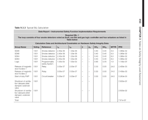
Data Report – Instrumented Safety Function Implementation Requirements
DC S 0.40 0.40 0.40 0.40 0.90 0.30 0.30 0.00
β D – – – – – – – – – –
β – – – – – – – – – –
Required SIL: 1 The loop consists of four smoke detectors voted as 2oo4, one fire and gas logic controller and four actuators as listed in Table below Calculation Data and Architectural Constraints on Hardware Safety Integrity Data: λ D 1.30e-06 1.30e-06 1.30e-06 1.30e-06 1.00e-05 2.00e-07 2.00e-07 3.00e-07
2.40e-06 2.40e-06 2.40e-06 2.40e-06 1.00e-05 3.00e-07 3.00e-07 5.00e-07
λ S Reference Smoke detector Smoke detector Smoke detector Smoke detector Programmable safety System Circuit breaker
Table 9.3.3 Typical SIL Calculation Voting Group Name 1001 SD95 1001 SD66 1001 SD64 1001 SD63 1001 Logic Relay 1001 Release of magnetic door holders 1 Relay 1001 Release of magnetic door holders 2 1001 Start of duty FWP 1001 Shutdown of ventila- tion dampers (inlet damper) + solenoid valve 1001 Shutdown of ventila- tion dampers (inlet damper) + solenoid valve Total