
Page 135 - Op Amps Design, Applications, and Troubleshooting
P. 135
118 AMPLIFIERS
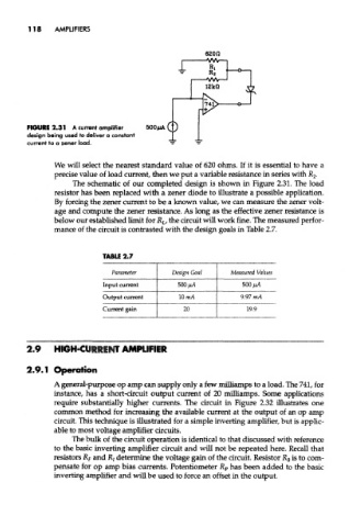
FIGURE 2.31 A current amplifier
design being used to deliver a constant
current to a zener load.
We will select the nearest standard value of 620 ohms. If it is essential to have a
precise value of load current, then we put a variable resistance in series with JR 2-
The schematic of our completed design is shown in Figure 2.31. The load
resistor has been replaced with a zener diode to illustrate a possible application.
By forcing the zener current to be a known value, we can measure the zener volt-
age and compute the zener resistance. As long as the effective zener resistance is
below our established limit for R L, the circuit will work fine. The measured perfor-
mance of the circuit is contrasted with the design goals in Table 2.7.
TABU 2.7
Parameter Design Goal Measured Values
Input current 500 jM 500 fiA
Output current 10mA 9.97 mA
Current gain 20 19.9
2.9 HIGH-CURRENT AMPLIFIER
2.9.1 Operation
A general-purpose op amp can supply only a few milliamps to a load. The 741, for
instance, has a short-circuit output current of 20 milliamps. Some applications
require substantially higher currents. The circuit in Figure 2.32 illustrates one
common method for increasing the available current at the output of an op amp
circuit. This technique is illustrated for a simple inverting amplifier, but is applic-
able to most voltage amplifier circuits.
The bulk of the circuit operation is identical to that discussed with reference
to the basic inverting amplifier circuit and will not be repeated here. Recall that
resistors R F and R/ determine the voltage gain of the circuit. Resistor K 8 is to com-
pensate for op amp bias currents. Potentiometer R P has been added to the bask
inverting amplifier and will be used to force an offset in the output.