
Page 139 - Op Amps Design, Applications, and Troubleshooting
P. 139
122 AMPLIFIERS
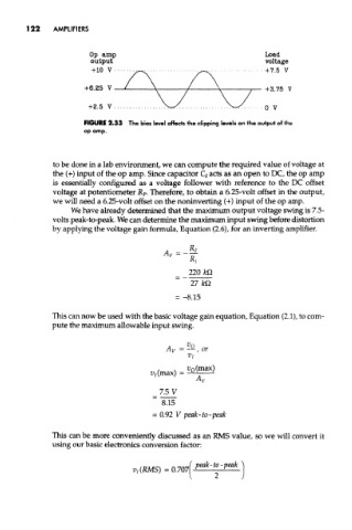
FIGURE 2.33 The bias level affects the clipping levels on the output of the
op amp.
to be done in a lab environment, we can compute the required value of voltage at
the (+) input of the op amp. Since capacitor Q acts as an open to DC, the op amp
is essentially configured as a voltage follower with reference to the DC offset
voltage at potentiometer R P. Therefore, to obtain a 6.25-volt offset in the output,
we will need a 6.25-volt offset on the noninverting (+) input of the op amp.
We have already determined that the maximum output voltage swing is 7.5-
volts peak-to-peak. We can determine the maximum input swing before distortion
by applying the voltage gain formula, Equation (2.6), for an inverting amplifier.
This can now be used with the basic voltage gain equation, Equation (2.1), to com-
pute the maximum allowable input swing.
This can be more conveniently discussed as an RMS value, so we will convert it
using our basic electronics conversion factor: