
Page 206 - Op Amps Design, Applications, and Troubleshooting
P. 206
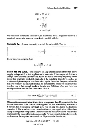
Voltage-Controlled Oscillator  189


         We will select a standard value of 0.033-microfarad for Q. If greater accuracy is
         required, we can add a second capacitor in parallel with Q.

         Compute ^4.   JR 4 must be exactly one-half the value of Rj. That is,


        Select the Op Amp. The primary op amp characteristic (other than power
        supply voltage, etc.) in this application is slew rate. If the output of AI tries to
        change faster than the slew rate will allow, the actual operating frequency will be
        lower than originally predicted. Similarly, if the switching times for A 2 and A 3 are
        a substantial percentage of one alternation, again, the actual frequency of oscilla-
        tion will be below the calculated value. To minimize this effect, we can ensure that
        the slew rate is fast enough to allow the rise and fall times of A 2 and A 3 to be a
        small part of the time for one alternation. That is,


        This equation ensures that switching time is no greater than 20 percent of the time
        for one alternation. If the factor 40 is changed to 200, this relationship is reduced to
        1 percent, but it requires a very high slew rate op amp to achieve moderate fre-
        quencies. If this is an important consideration for your application, think about
        using an integrated comparator. These devices are readily available with switch-
        ing times in the range of tens of nanoseconds. For our present design, however, let
        us determine the required slew rate for a 20-percent rise time factor: