
Page 222 - Op Amps Design, Applications, and Troubleshooting
P. 222
204 OSCILLATORS
4.5 TRIANGLE-WAVE OSCILLATOR
4.5.1 Operation
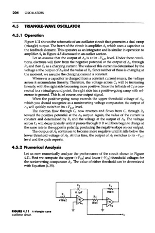
Figure 4.11 shows the schematic of an oscillator circuit that generates a dual ramp
(triangle) output. The heart of the circuit is amplifier AI which uses a capacitor as
the feedback element. This operates as an integrator and is similar in operation to
amplifier AI in Figure 4.5 discussed in an earlier section.
Let us assume that the output of A 2 is at its -V SAT level. Under these condi-
tions, electrons will flow from the negative potential at the output of A 2f through
RI and then Q as a charging current. The value of this current is determined by the
voltage at the output of A 2 and the value of Rj. Since neither of these is changing at
the moment, we assume the charging current is constant.
Whenever a capacitor is charged from a constant current source, the voltage
across it accumulates linearly. Therefore, the voltage across Q will be increasing
linearly, with the right side becoming more positive. Since the left side of Q is con-
nected to a virtual ground point, the right side has a positive-going ramp with ref-
erence to ground. This is, of course, our output signal.
When the positive-going ramp exceeds the upper threshold voltage of A 2,
which you should recognize as a noninverting voltage comparator, the output of
A 2 will quickly switch to its +V SAT level.
The electron flow through Q now reverses and flows from Q through Rj
toward the positive potential at the A 2 output. Again, the value of the current is
constant and determined by RI and the voltage at the output of A 2. The voltage
across Q will decay linearly until it passes through 0. It will then begin to charge at
the same rate in the opposite polarity, producing the negative slope on our output.
The output of AI continues to become more negative until it falls below the
lower threshold voltage of A 2. At this time, the output of A 2 switches to its -V SAT
level and the cycle repeats.
4.5.2 Numerical Analysis
Let us now numerically analyze the performance of the circuit shown in Figure
4.11. First we compute the upper (+VTH) and lower (~V TH) threshold voltages for
the noninverting comparator A 2. The value of either threshold can be determined
with Equation (4.35).
FIGURE 4.11 A triangle-wave
oscillator circuit.