
Page 220 - Op Amps Design, Applications, and Troubleshooting
P. 220
202 OSCILLATORS
This is below the 0.5-volts-per-microsecond slew rate of the 741 op amp, so let us
select this device for our design,
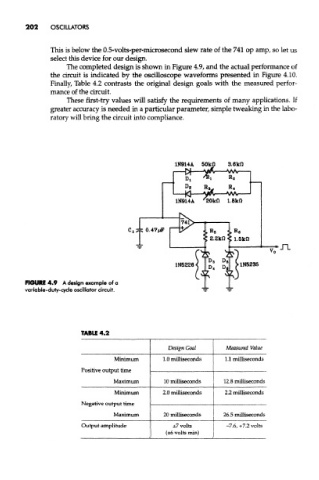
The completed design is shown in Figure 4.9, and the actual performance of
the circuit is indicated by the oscilloscope waveforms presented in Figure 4.10.
Finally, Table 4.2 contrasts the original design goals with the measured perfor-
mance of the circuit.
These first-try values will satisfy the requirements of many applications. If
greater accuracy is needed in a particular parameter, simple tweaking in the labo-
ratory will bring the circuit into compliance.
FIGURE 4.9 A design example of a
variable-duty-cycle oscillator circuit.
TABLE 4.2
Design Goal Measured Value
Minimum 1.0 milliseconds 1.1 milliseconds
Positive output time
Maximum 10 milliseconds 12.8 milliseconds
Minimum 2.0 milliseconds 2.2 milliseconds
Negative output time
Maximum 20 milliseconds 26.5 milliseconds
Output amplitude ±7 volts -7.6, +7.2 volts
(±6 volts min)