
Page 215 - Op Amps Design, Applications, and Troubleshooting
P. 215
Variable-Duty Cycle 197
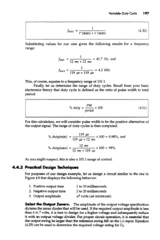
Substituting values for our case gives the following results for a frequency
range:
This, of course, equates to a frequency range of 101:1.
Finally, let us determine the range of duty cycles. Recall from your basic
electronics theory that duty cycle is defined as the ratio of pulse width to total
period.
For this calculation, we will consider pulse width to be the positive alternation of
the output signal. The range of duty cycles is then computed.
As you might suspect, this is also a 101:1 range of control.
4.4.3 Practical Design Techniques
For purposes of our design example, let us design a circuit similar to the one in
Figure 4.8 that displays the following behavior:
1. Positive output time 1 to 10 milliseconds
2. Negative output time 2 to 20 milliseconds
3. Output amplitude ±7 volts (±6 minimum)
Select the Output Zeners. The amplitude of the output voltage specification
dictates the zener diodes that will be used. If the required output amplitude is less
than 6 to 7 volts, it is best to design for a higher voltage and subsequently reduce
it with an output voltage divider. For proper circuit operation, it is essential that
the output swing be larger than the reference swing felt on the (+) input. Equation
(4.25) can be used to determine the required voltage rating for D 5.