
Page 219 - Op Amps Design, Applications, and Troubleshooting
P. 219
Variable-Duty Cycle 201
We will select a standard value of 3.6 kilohms for R 2.
Finally, we compute the value of RI by applying Equation (4.28).
The nearest standard value for RI is 25 kilohms. It might be a better choice, how-
ever, to go to the next higher value so we can be sure that the maximum pulse
width in our original design goal can be achieved. With this in mind, let us select
a 50-kilohm variable resistor for R lt
Select D} and Oj. Diodes D l and D 2 are simple isolation diodes and have no
critical characteristics as long as the V PIV rating of the diode exceeds about 30 volts
and the I F rating is greater than the J 0s rating of the op amp. We will use 1N914A
diodes for our example design.
Select the Op Amp. The primary op amp parameter that must be considered
in this application is the slew rate. If the slew rate causes the rise and fall times of
the output waveform to be a significant part of either alternation, then the alterna-
tion will be longer than originally predicted.
For purposes of our present example, let us accept a rise and fall time of 10
percent of the shortest alternation period. In our case, this means that the rise and
fall times can be no longer than 10 percent of 1 millisecond, or 100 microseconds.
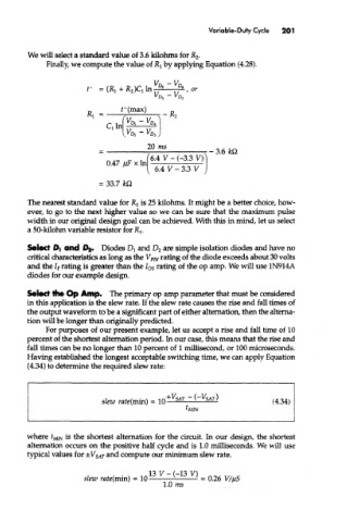
Having established the longest acceptable switching time, we can apply Equation
(4.34) to determine the required slew rate:
where t Mm is the shortest alternation for the circuit In our design, the shortest
alternation occurs on the positive half cycle and is 1.0 milliseconds. We will use
typical values for ±V SAT and compute our minimum slew rate.