
Page 430 - Op Amps Design, Applications, and Troubleshooting
P. 430
406 SPECIALIZED DEVICES
4. Input impedance is very high.
5. Output impedance is very low.
6. Common-mode rejection is very high.
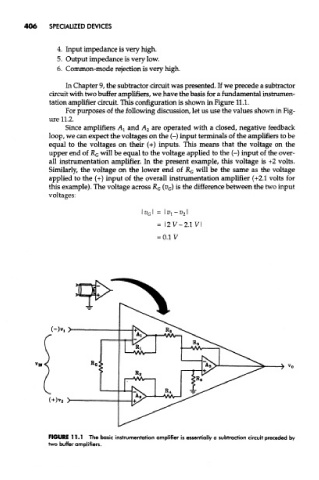
In Chapter 9, the subtracter circuit was presented. If we precede a subtracter
circuit with two buffer amplifiers, we have the basis for a fundamental instrumen-
tation amplifier circuit. This configuration is shown in Figure 11.1.
For purposes of the following discussion, let us use the values shown in Fig-
ure 11.2.
Since amplifiers A\ and A 2 are operated with a closed, negative feedback
loop, we can expect the voltages on the (-) input terminals of the amplifiers to be
equal to the voltages on their (+) inputs. This means that the voltage on the
upper end of R G will be equal to the voltage applied to the (-) input of the over-
all instrumentation amplifier. In the present example, this voltage is +2 volts.
Similarly, the voltage on the lower end of R G will be the same as the voltage
applied to the (+) input of the overall instrumentation amplifier (+2.1 volts for
this example). The voltage across R G (V G) is the difference between the two input
voltages:
FIGURE 11.1 The basic instrumentation amplifier is essentially a subtraction circuit preceded by
two buffer amplifiers.