
Page 434 - Op Amps Design, Applications, and Troubleshooting
P. 434
410 SPECIALIZED DEVICES
Whether the amplifiers are constructed from discrete components or pur-
chased in an integrated form, the bask operation remains the same. In the case of
the log amp, the output voltage is proportional to the logarithm of the input volt-
age. This relationship is obtained by utilizing the logarithmic relationship that
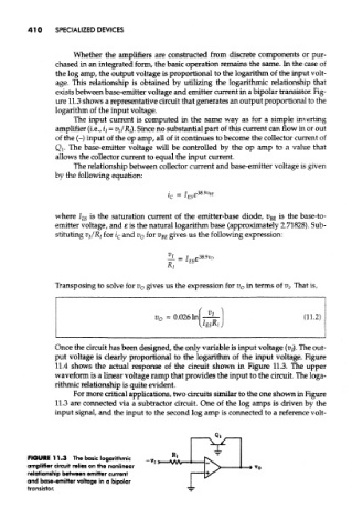
exists between base-emitter voltage and emitter current in a bipolar transistor. Fig-
ure 11.3 shows a representative circuit that generates an output proportional to the
logarithm of the input voltage.
The input current is computed in the same way as for a simple inverting
amplifier (i.e., ij = Vj/Rj). Since no substantial part of this current can flow in or out
of the (-) input of the op amp, all of it continues to become the collector current of
Qi. The base-emitter voltage will be controlled by the op amp to a value that
allows the collector current to equal the input current.
The relationship between collector current and base-emitter voltage is given
by the following equation:
where I 2S is the saturation current of the emitter-base diode, V BE is the base-to-
emitter voltage, and e is the natural logarithm base (approximately 2.71828). Sub-
stituting VI/RI for i c and v 0 for V BE gives us the following expression:
Transposing to solve for v o gives us the expression for v 0 in terms of Vj. That is,
Once the circuit has been designed, the only variable is input voltage (t?j). The out-
put voltage is clearly proportional to the logarithm of the input voltage. Figure
11.4 shows the actual response of the circuit shown in Figure 11.3, The upper
waveform is a linear voltage ramp that provides the input to the circuit. The loga-
rithmic relationship is quite evident.
For more critical applications, two circuits similar to the one shown in Figure
11.3 are connected via a subtracter circuit. One of the log amps is driven by the
input signal, and the input to the second log amp is connected to a reference volt-
FIGURE 11.3 The basic logarithmic
amplifier circuit relies on the nonlinear
relationship between emitter current
and base-emitter voltage in a bipolar
transistor.