
Page 436 - Op Amps Design, Applications, and Troubleshooting
P. 436
412 SPECIALIZED DEVICES
mic amplifier (as shown in Figure 11.4), it would emerge as a logarithmic curve
(similar in shape to the familiar RC time constant curve). If this logarithmic signal
were then passed through an analog amplifier, the output would again be a linear
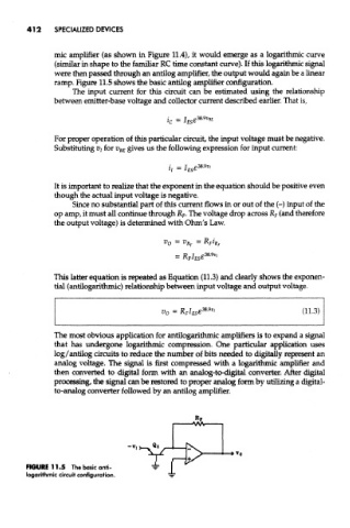
ramp. Figure 11.5 shows the basic antilog amplifier configuration.
The input current for mis circuit can be estimated using the relationship
between emitter-base voltage and collector current described earlier. That is,
For proper operation of this particular circuit, the input voltage must be negative.
Substituting Vj for V BE gives us the following expression for input current:
It is important to realize that the exponent in the equation should be positive even
though the actual input voltage is negative.
Since no substantial part of this current flows in or out of the (-) input of the
op amp, it must all continue through R F, The voltage drop across R F (and therefore
the output voltage) is determined with Ohm's Law.
This latter equation is repeated as Equation (11.3) and clearly shows the exponen-
tial (antilogarithmic) relationship between input voltage and output voltage.
The most obvious application for antilogarithmic amplifiers is to expand a signal
that has undergone logarithmic compression. One particular appEcation uses
log/antilog circuits to reduce the number of bits needed to digitally represent an
analog voltage. The signal is first compressed with a logarithmic amplifier and
then converted to digital form with an analog-to-digital converter. After digital
processing, the signal can be restored to proper analog form by utilizing a digital-
to-analog converter followed by an antilog amplifier.
FJGURE11.5 The basic anti-
logarithmic circuit configuration.