
Page 438 - Op Amps Design, Applications, and Troubleshooting
P. 438
414 SPECIALIZED DEVICES
where k is a constant determined by the circuit configuration. Substitution of this
latter equation into the preceding equation gives us a form that reveals the multi-
plier action of the multiplier circuit.
Here we can see that the output voltage is clearly a result of multiplying the input
voltages together with a circuit constant. The value of the constant (k) is typically
0.1.
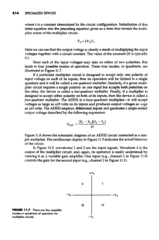
Since each of the input voltages may take on either of two polarities, this
leads to four possible modes of operation. These four modes, or quadrants, are
illustrated in Figure 11.7.
If a particular multiplier circuit is designed to accept only one polarity of
input voltage on each of its inputs, then its operation will be limited to a single
quadrant and it will be called a one-quadrant multiplier. Similarly, if a given multi-
plier circuit requires a single polarity on one input but accepts both polarities on
the other, the device is called a two-quadrant multiplier. Finally, if a multiplier is
designed to accept either polarity on both of its inputs, then the device is called a
four-quadrant multiplier. The AD532 is a four-quadrant multiplier—it will accept
voltages as large as ±10 volts on its inputs and produces output voltages as large
as ±10 volts. The AD532 employs differential inputs and generates a single-ended
output voltage described by the following expression:
Figure 11.8 shows the schematic diagram of an AD532 circuit connected as a sim-
ple multiplier. The oscilloscope display in Figure 11.9 indicates the actual behavior
of the circuit.
In Figure 11.9, waveforms 1 and 2 are the input signals. Waveform 4 is the
output of the multiplier circuit, and, again, its operation is easily understood by
viewing it as a variable gain amplifier. One input (e.g., channel 1 in Figure 11.9)
controls the gain for the second input (e.g., channel 2 in Figure 11.9).
FIGURE 11.7 There are four possible
modes or quadrants of operation for
multiplier circuits.