
Page 437 - Op Amps Design, Applications, and Troubleshooting
P. 437
Multipliers/Dividers 413
Although the average technician or engineer can easily construct one of
these circuits in the laboratory and confirm logarithmic operation, the design of a
reliable circuit that is minimally affected by temperature and other nonideal con-
ditions is anything but trivial. In most cases, the designer should consider
employing a logarithmic device produced commercially. Such devices contain
closely matched components, track well with temperature, and are generally easy
to implement Additionally, the cost is very reasonable for many applications.
The model 755, 6-decade, high-accuracy, wideband log/antilog amplifier
manufactured by Analog Devices, Inc., is an example of a commercially available
logarithmic module. It requires no external components and can be configured to
produce either a logarithmic or an antilogarithmic response. It comes as a module
that is about 1.5 inches on a side and 0.4 inches thick.
5 MULTIPLIERS/DIVIDERS
Multiplier/divider circuits can be constructed from standard op amps and discrete
components. However, the low cost and high performance of integrated circuit
versions of these devices makes discrete designs a very unattractive alternative in
most cases. In this section, we will make frequent reference to the AD532 Integrated
Circuit Multiplier manufactured by Analog Devices (see Figure 11.6).
Regardless of the type of analog multiplier being considered, the device is
essentially a variable gain amplifier—one of the multiplier inputs is amplified by
the circuit and appears in the output, and the other is used to control the gain of
the circuit. For example, if we assume that the inputs to the multiplier circuit
shown in Figure 11.6 are voltages called V x and F y, and we further assume that
the gain of the circuit (A v) is established by V x, then the output of the circuit can
be expressed as
In this form, the device appears to be a simple linear amplifier whose output is
determined by the input voltage times a voltage gain. However, the voltage gain is
not constant in the case of a multiplier circuit. More specifically, it is determined
by the voltage applied to one of the inputs (V x is the present example) and so can
be expressed as
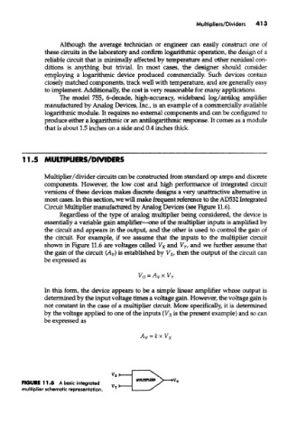
FIGURE 11.6 A basic integrated
multiplier schematic representation.