
Page 148 - Optical Communications Essentials
P. 148
Connectors and Splices
138 Chapter Eight
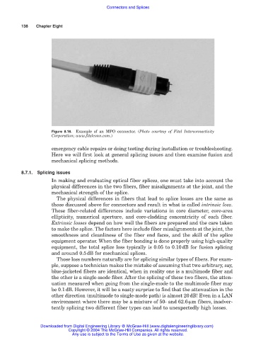
Figure 8.16. Example of an MPO connector. (Photo courtesy of Fitel Interconnectivity
Corporation; www.fitelconn.com.)
emergency cable repairs or doing testing during installation or troubleshooting.
Here we will first look at general splicing issues and then examine fusion and
mechanical splicing methods.
8.7.1. Splicing issues
In making and evaluating optical fiber splices, one must take into account the
physical differences in the two fibers, fiber misalignments at the joint, and the
mechanical strength of the splice.
The physical differences in fibers that lead to splice losses are the same as
those discussed above for connectors and result in what is called intrinsic loss.
These fiber-related differences include variations in core diameter, core-area
ellipticity, numerical aperture, and core-cladding concentricity of each fiber.
Extrinsic losses depend on how well the fibers are prepared and the care taken
to make the splice. The factors here include fiber misalignments at the joint, the
smoothness and cleanliness of the fiber end faces, and the skill of the splice
equipment operator. When the fiber bonding is done properly using high-quality
equipment, the total splice loss typically is 0.05 to 0.10dB for fusion splicing
and around 0.5dB for mechanical splices.
Those loss numbers naturally are for splicing similar types of fibers. For exam-
ple, suppose a technician makes the mistake of assuming that two arbitrary, say,
blue-jacketed fibers are identical, when in reality one is a multimode fiber and
the other is a single-mode fiber. After the splicing of these two fibers, the atten-
uation measured when going from the single-mode to the multimode fiber may
be 0.1dB. However, it will be a nasty surprise to find that the attenuation in the
other direction (multimode to single-mode path) is almost 20dB! Even in a LAN
environment where there may be a mixture of 50- and 62.6-µm fibers, inadver-
tently splicing two different fiber types can lead to unexpectedly high losses.
Downloaded from Digital Engineering Library @ McGraw-Hill (www.digitalengineeringlibrary.com)
Copyright © 2004 The McGraw-Hill Companies. All rights reserved.
Any use is subject to the Terms of Use as given at the website.