
Page 149 - Optical Communications Essentials
P. 149
Connectors and Splices
Connectors and Splices 139
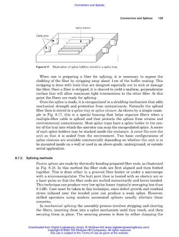
Figure 8.17. Illustration of splice holders stored in a splice tray.
When one is preparing a fiber for splicing, it is necessary to expose the
cladding of the fiber by stripping away about 1cm of the buffer coating. This
stripping is done with tools that are designed especially not to nick or damage
the fiber. Once a fiber is stripped, it is cleaved to yield a uniform, perpendicular
surface that will allow maximum light transmission to the other fiber. At this
point the fibers are ready for splicing.
Once the splice is made, it is encapsulated in a shielding mechanism that adds
mechanical strength and protection from contaminants. Normally the spliced
fiber then is stored in a splice tray or splice closure. As shown by a simple exam-
ple in Fig. 8.17, this is a special housing that helps organize fibers when a
multiple-fiber cable is spliced and that protects the splices from strains and
environmental contaminants. Most splice trays have a splice holder in the cen-
ter of the tray into which the operator can snap the encapsulated splice. A series
of such splice holders may be stacked inside the enclosure. A cover fits over the
unit so that it is sealed from the environment. Two basic configurations of
splice closures are available commercially depending on whether the unit is to
be mounted inside on a wall or used in an above-grade, underground, or outside
aerial application.
8.7.2. Splicing methods
Fusion splices are made by thermally bonding prepared fiber ends, as illustrated
in Fig. 8.18. In this method the fiber ends are first aligned and then butted
together. This is done either in a grooved fiber holder or under a microscope
with a micromanipulator. The butt joint then is heated with an electric arc or
a laser pulse so that the fiber ends are melted momentarily and hence bonded.
This technique can produce very low splice losses (typically averaging less than
0.1 dB). Care must be taken in this technique, since defect growth and residual
stress induced near the bonded joint can produce a weak splice. However,
skilled operators using modern automated splicers usually alleviate these
concerns.
In mechanical splicing the assembly process involves stripping and cleaving
the fibers, inserting them into a splice mechanism until they touch, and then
securing them in place. The securing process is done by either clamping the
Downloaded from Digital Engineering Library @ McGraw-Hill (www.digitalengineeringlibrary.com)
Copyright © 2004 The McGraw-Hill Companies. All rights reserved.
Any use is subject to the Terms of Use as given at the website.