
Page 150 - Optical Communications Essentials
P. 150
Connectors and Splices
140 Chapter Eight
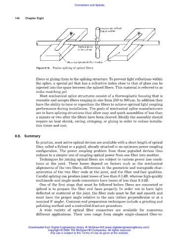
Figure 8.18. Fusion splicing of optical fibers.
fibers or gluing them to the splicing structure. To prevent light reflections within
the splice, a special gel that has a refractive index close to that of glass can be
injected into the space between the spliced fibers. This material is referred to as
index-matching gel.
Most mechanical splice structures consist of a thermoplastic housing that is
versatile and accepts fibers ranging in size from 250 to 900µm. In addition they
have the ability to tune or reposition the fibers to achieve optimal light coupling
performance during installation. The goals of mechanical splice manufacturers
are to have splicing structures that allow easy and quick assemblies of less than
a minute or two after the fibers have been cleaved. Ideally the assembly should
require no heat shrink, curing, crimping, or gluing in order to reduce installa-
tion times and cost.
8.8. Summary
In practice, most active optical devices are available with a short length of optical
fiber, called a flylead or a pigtail, already attached in an optimum power coupling
configuration. The power coupling problem from these pigtailed devices thus
reduces to a simpler one of coupling optical power from one fiber into another.
Techniques for joining optical fibers are subject to various power loss condi-
tions at the joint. These losses depend on factors such as the mechanical
alignments of the two fibers, differences in the geometric and waveguide char-
acteristics of the two fiber ends at the joint, and the fiber end-face qualities.
Careful splicing can produce joint losses of less than 0.1dB, whereas high-quality
multimode and single-mode connectors have losses of less than 0.3dB.
One of the first steps that must be followed before fibers are connected or
spliced is to prepare the fiber end faces properly. In order not to have light
deflected or scattered at the joint, the fiber ends must be flat and smooth and
must have the proper angle relative to the axis (either perpendicular or at a
nominal 8° angle). Common end preparation techniques include a grinding and
polishing method and a controlled-fracture procedure.
A wide variety of optical fiber connectors are available for numerous
different applications. Their uses range from simple single-channel fiber-to-
Downloaded from Digital Engineering Library @ McGraw-Hill (www.digitalengineeringlibrary.com)
Copyright © 2004 The McGraw-Hill Companies. All rights reserved.
Any use is subject to the Terms of Use as given at the website.