
Page 158 - Optical Communications Essentials
P. 158
Passive Optical Components
148 Chapter Nine
Since the couplers are available in different grade qualities, vendor data sheets
will have exact values for a specific coupler configuration.
9.1.3. Tap coupler
To monitor the light signal level or quality in a link, one can use a 2 2 device
that has a coupling fraction of around 1 to 5 percent, which is selected and fixed
during fabrication. This is known as a tap coupler. Nominally the tap coupler is
packaged as a three-port device with one arm of the 2 2 coupler being termi-
nated inside the package. This termination might use the specialty attenuating
fiber described in Sec. 4.7. Figure 9.2 shows a typical package for such a tap cou-
pler, and Table 9.2 lists some representative specifications.
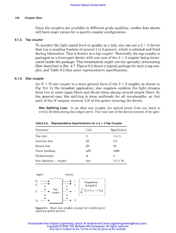
9.1.4. Star coupler
An N N star coupler is a more general form of the 2 2 coupler, as shown in
Fig. 9.3. In the broadest application, star couplers combine the light streams
from two or more input fibers and divide them among several output fibers. In
the general case, the splitting is done uniformly for all wavelengths, so that
each of the N outputs receives 1/N of the power entering the device.
Star Splitting Loss In an ideal star coupler, the optical power from any input is
evenly divided among the output ports. The total loss of the device consists of its split-
TABLE 9.2. Representative Specifications for a 2 2 Tap Coupler
Parameter Unit Specification
Tap ratio % 1 to 5
Insertion loss dB 0.5
Return loss dB 55
Power handling mW 1000
Flylead length m 1
Size (diameter length) mm 5.5 35
Figure 9.3. Basic star coupler concept for combining or
splitting optical powers.
Downloaded from Digital Engineering Library @ McGraw-Hill (www.digitalengineeringlibrary.com)
Copyright © 2004 The McGraw-Hill Companies. All rights reserved.
Any use is subject to the Terms of Use as given at the website.